

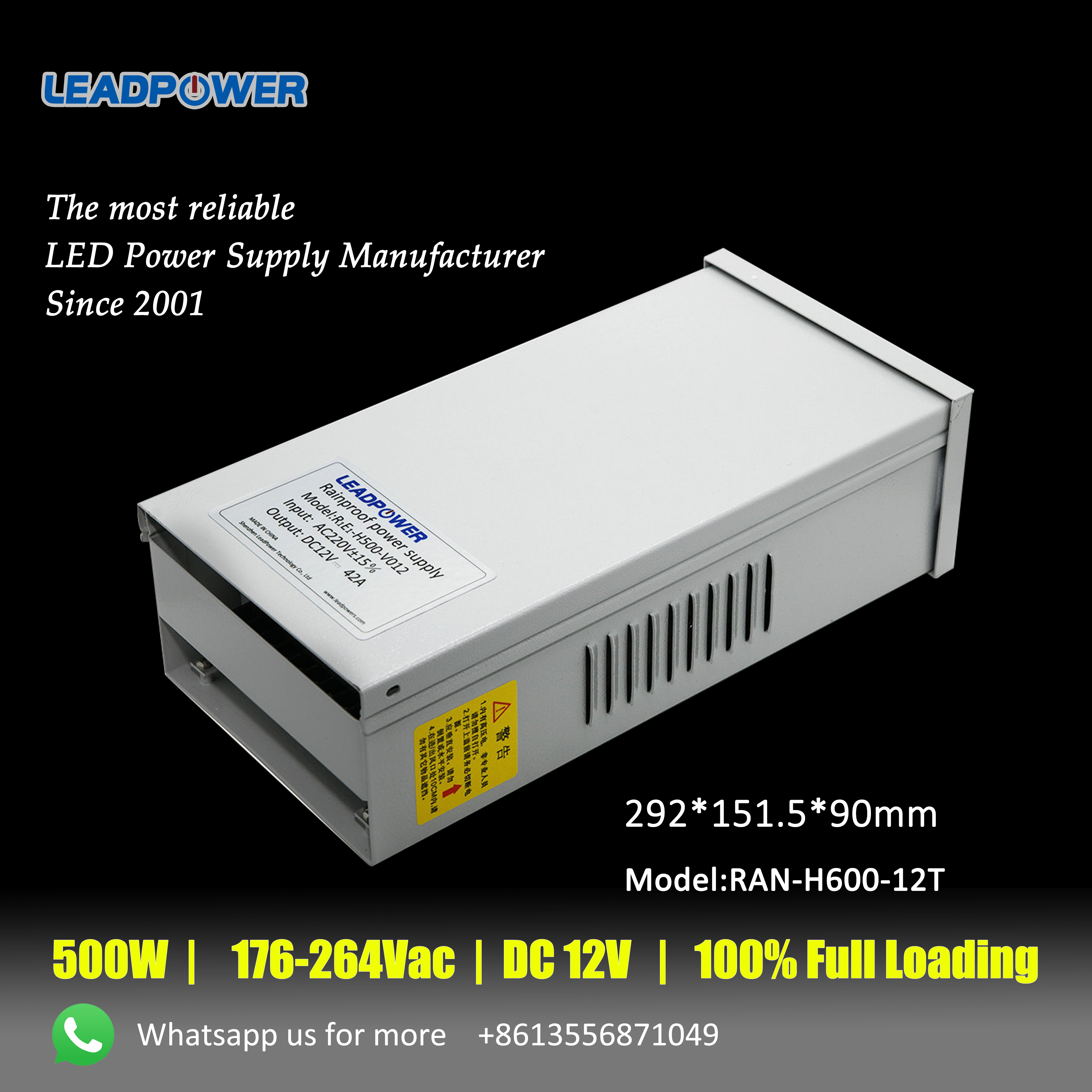
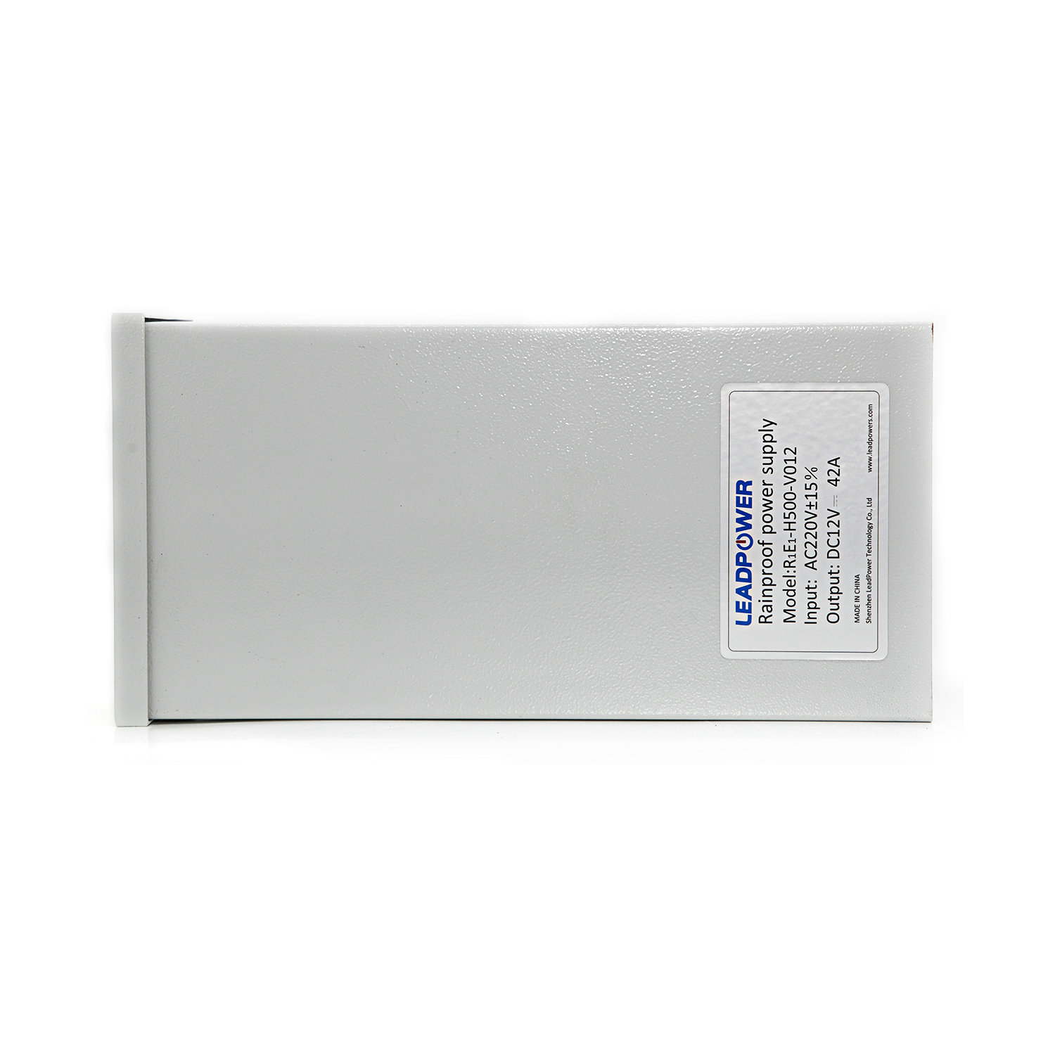
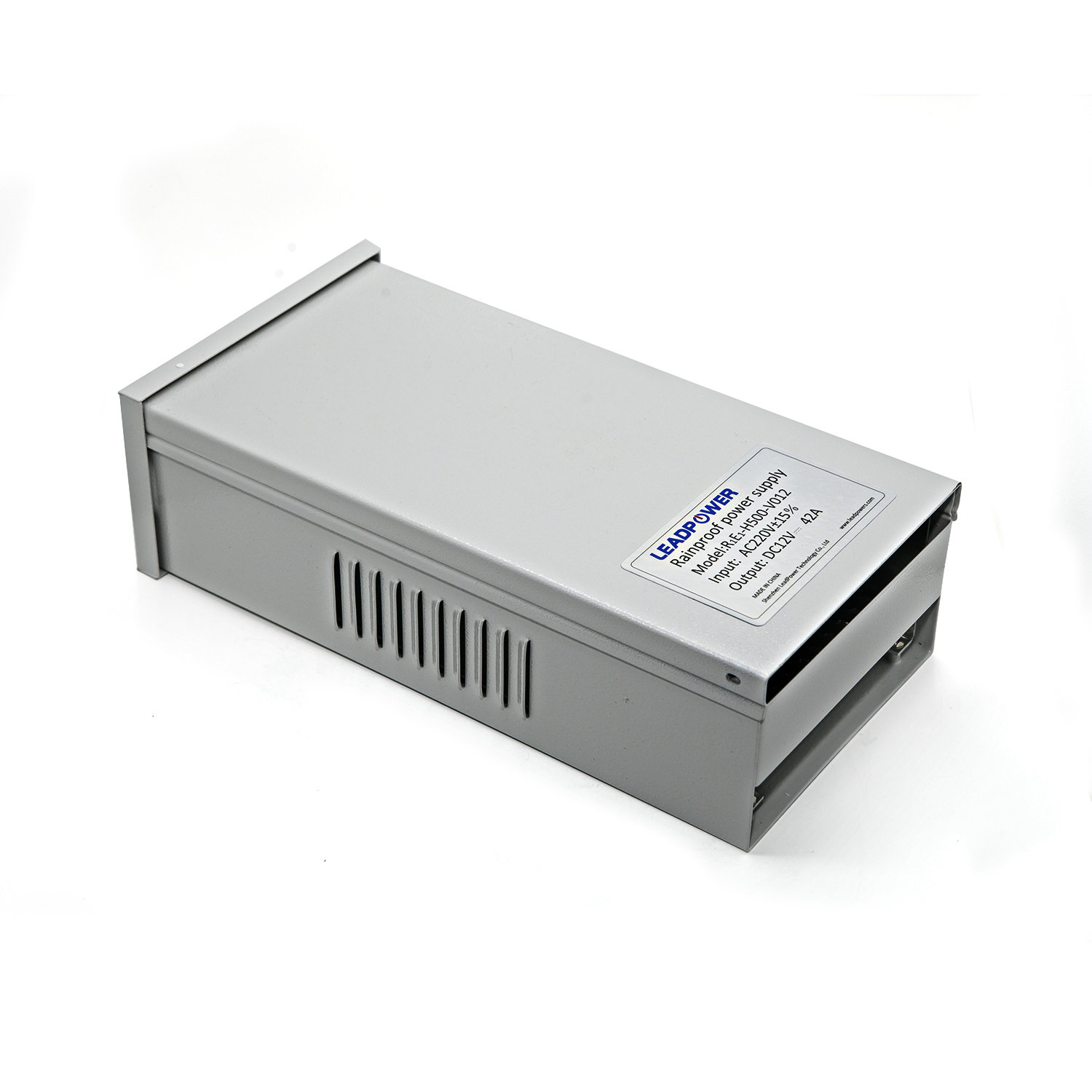

| Model | RAN-H500-V012 | ||||
| Input | Rated Input Voltage | 200-240/ 100-120VAC | |||
| Input Voltage Range | 190~264/ 90~130Vac | ||||
| Frequency Range | 47~63(Typ. 50/60)HZ | ||||
| Max. Input Current | ≤8A | ||||
| Inrush Current | ≤110A | ||||
| Output | Rated output voltage | 12V | |||
| Rated Output Current | 42A | ||||
| Max. Output Power | 504W | ||||
| Efficiency | ≥87%(Typ. 88%) | ||||
| Output Ripple & Noise | ≤300mVp-p | ||||
| Dynamic Response Overshoot | ≤5% | ||||
| Dynamic Response Recovery Time | 200μs | ||||
| Line regulation | ±1% | ||||
| Load regulation | ±2% | ||||
| Voltage tolerance | ±2% | ||||
| Environment Condition | Range of working temperature | -20~+50(Typ.25) | |||
| Storage temperature | -40~+80(Typ. 25) | ||||
| Relative Humidity | 5~90% | ||||
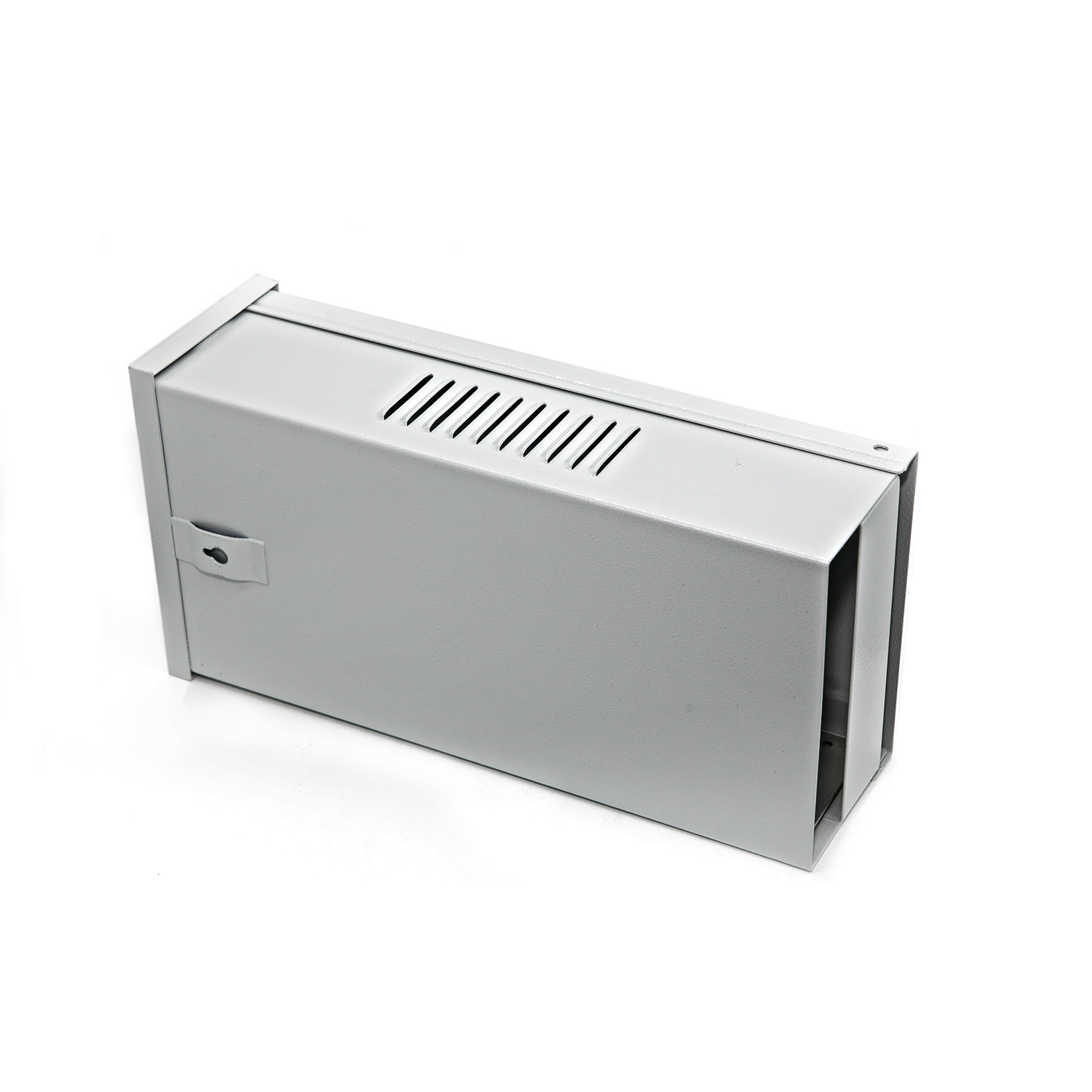
| Cooling Method | Forced-Air Cooling | Built-in fan (do not block the air duct of the fan when using, so as not to affect normal use) | |||
| Atmospheric Pressure | 70~106Kpa | ||||
| Altitude | 0~3000m | ||||
| Safety &EMC | Leakage Current | Input To FG | ≤3.5mA | 240Vac/60Hz | |
| Input To Output | ≤0.25mA | ||||
| Dielectrical Strength | Input To Output | 1500Vac/10mA/1min | No arc, no breakdown |
||
| Input To FG | 1500Vac/10mA/1min | ||||
| Output To FG | 500Vac/10mA/1min | ||||
| Insulation resistance | Input To Output | ≥10MΩ@ 500Vdc | 1atm, 90%RH, 500VDC | ||
| Input To FG | ≥10MΩ@ 500Vdc | ||||
| Output To FG | ≥10MΩ@ 500Vdc | ||||
| Safety Standards | UL60950,IEC/EN60950, GB4943.1-2011 | ||||
| EMS | Surge:IEC61000-4-5 Line to Line:±2kV, Line to FG:±4kV | ||||
| Protection | Over voltge protection | ≤16V | Hiccup mode, recovers automatically after fault condition is removed. | ||
| Overload protection | 65~80A, Hiccup mode, recovers automatically after fault condition is removed. | ||||
| Over-temperature protection | /Optional | Ambient Temperature, Rated load | |||
| Output short-circuit protection | Recovers automatically after fault condition is removed. | ||||
| Reliability | MTBF | 25℃:100000Hrs,MIL-217 Method | |||
| Others | Cooling method | ⬜Ventilation Cooling √air cooling | |||
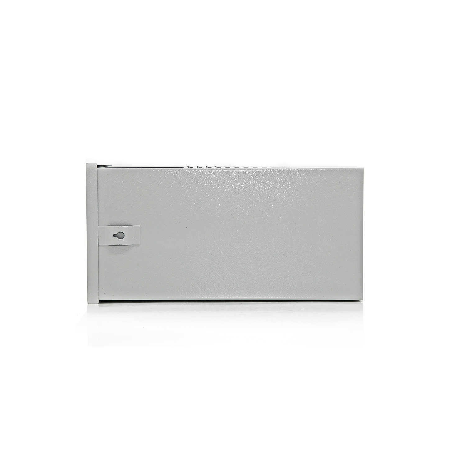
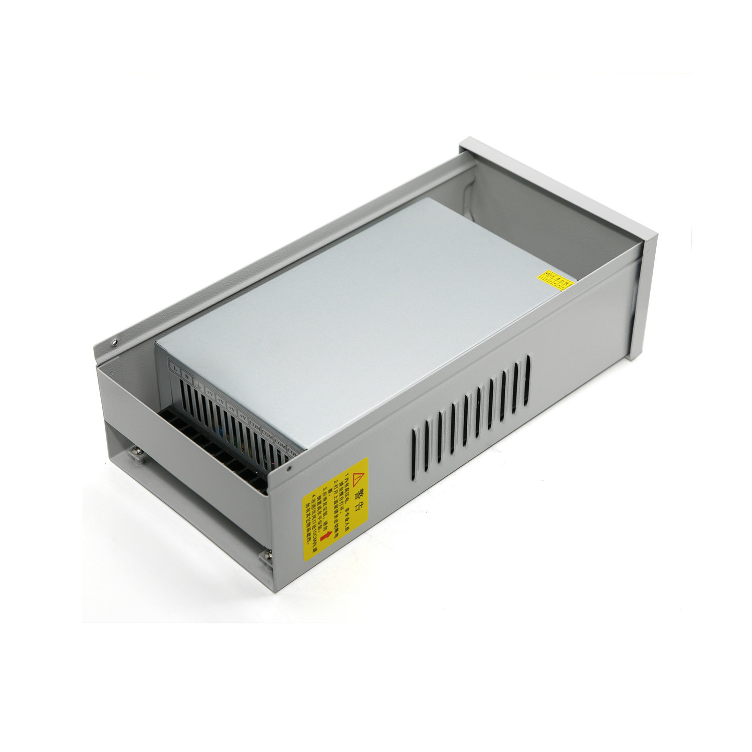
| Dimension | 292*151*90mm (L*W*H) | ||||
| Extension method | ⬜Three-proofing lacquer ⬜Stamped ⬜Low temperature start-up(-40℃)⬜Others |
||||
| Note | *Unless otherwise specified, all specifications are measured at an input of 230VAC, rated load, 25°C. *In order to extend the service life, it is recommended to leave an additional 30% margin when configuring the load. For example, if the device requires 100W of power, the power supply of not less than 130W is selected. * Switching power supply ripple test method: test on the power supply output terminal with a 20MHz oscilloscope, the ground length of the oscilloscope probe is not more than 12mm, and the probe input is paralleled with 47uF electrolytic capacitors and 0.1uF high frequency capacitors. *The power supply is part of the equipment system components, and all EMC tests need to be confirmed in conjunction with the end equipment for electromagnetic compatibility. |
||||

+8675523208269
jack_xu@leadpowers.com
https://www.leadpowers.com
+8675523208269
Unit 401-403,Block 5B,Skyworth Innovation Valley,Tangtou 1st Road ,Shiyan Street,Bao'an District, Shenzhen,China
